I started working on this post in April but never finished it. Here’s what I have: a wireless computer mouse, its bill of materials and a guess at how it works.
I picked up this 2.4 GHz wireless optical mouse at a Giant Tiger for about $10. It’s got a scroll wheel, scroll-click, left-click, right-click, and optical movement. An extra feature is the DPI button which toggles between 800 and 1600 dots per inch. For a bargain mouse it has impressive specs.
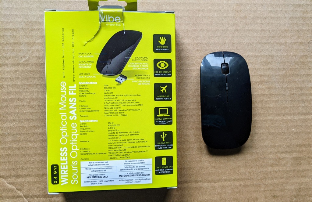
I took it apart using only a Philips screwdriver. I’m impressed to see that there are no screws in this product. My college professor taught me that the ideal number of screws in an electronic product is zero. This is not possible in complicated designs but for this wireless mouse it is clearly feasible.
Bill of Materials
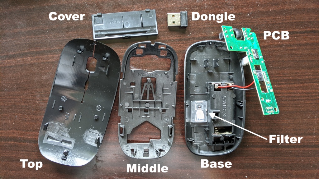
The seven distinct parts in the mouse are shown in Figure 1 and listed in Table 1 below.
| Part | Quantity |
| Base | 1 |
| Printed circuit board | 1 |
| Middle panel | 1 |
| Top panel | 1 |
| Battery cover | 1 |
| USB dongle | 1 |
| Optical filter | 1 |
The PCB fits into the base using snap fits. The optical filter is placed directly above the hole in the base and stays in place when the PCB is snug. The middle panel snaps over the base and the top panel snaps over the middle panel. On the rear side of the base, the dongle fits into a slot which is covered with the battery panel.
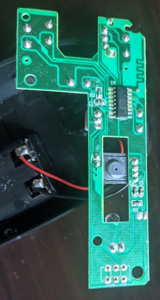
The mouse is powered by two AAA batteries and operates at a nominal 3 volts. I can’t confidently identify every single component on the PCB. Both sides of the board are shown in Figure 2 below. My best guess for its Bill of Materials is shown in Table 2.
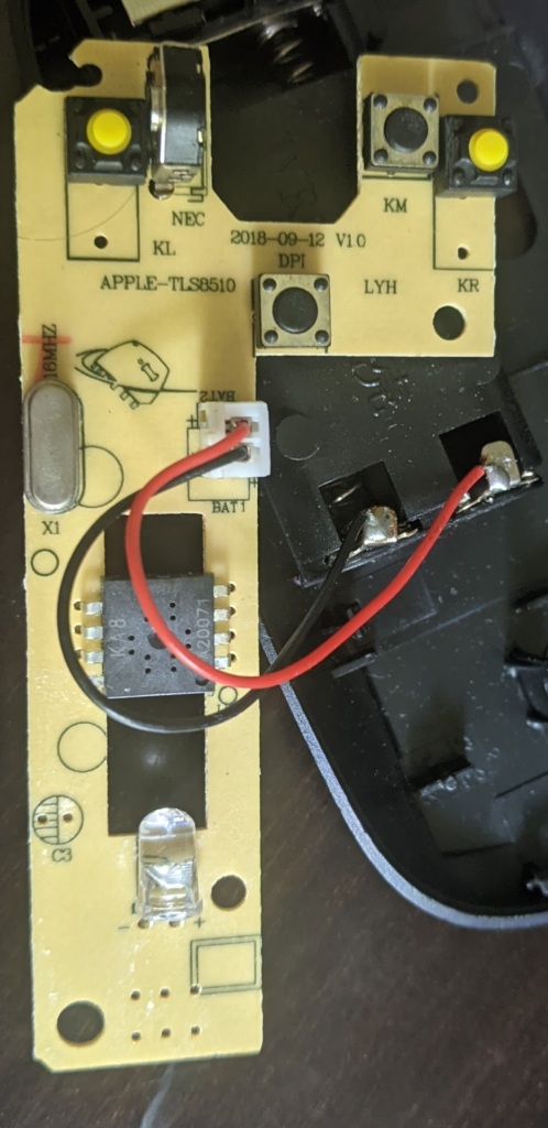
| Part | Part Number | Designator | Quantity |
| 2.4G ROM SoC | TLSR8510EP16 | U1 | 1 |
| Power header (including cable) | N/A | N/A | 1 |
| Yellow pushbuttons | N/A | KL, KR | 2 |
| Black pushbuttons | N/A | N/A | 2 |
| Scroll wheel (not shown) | N/A | N/A | 1 |
| Scroll wheel holder | N/A | NEC | 1 |
| Red LED | N/A | N/A | 1 |
| Capacitors | N/A | C1, C2, C3 | 3 |
| Resistor 47 Ω | N/A | R3 | 1 |
| Resistor 10 kΩ | N/A | R2 | 1 |
| Optical filter | N/A | N/A | 1 |
| 16 MHz Oscillator | 16B000J7AS | X1 | 1 |
| Motion Sensor | KA8 | U2 | 1 |
Operation
Here is my best guess of how the mouse operates. The power comes from the batteries onto the PCB via the power cable. The 16 MHz oscillator sets a clock for U1 and U2. The LED turns on with power. As its light enters the optical filter it can be seen on the base of the mouse. The refracted light somehow measures movement of the mouse using U1. U2 likely does calculations and transmits the degree of movement wirelessly to the computer via the dongle.
Similarly, the yellow pushbuttons transmit left and right clicks. The DPI is toggled between 800 and 1600 DPI when the black pushbutton is pressed. The scroll wheel is the most interesting part of the device. When the scroll wheel rotates the holder recognizes the degree of scroll and sends this information to U1. When the scroll wheel is clicked another black pushbutton recognizes the press.
